
- 📖 Geeky Medics OSCE Book
- ⚡ Geeky Medics Bundles
- ✨ 1300+ OSCE Stations
- ✅ OSCE Checklist PDF Booklet
- 🧠 UKMLA AKT Question Bank
- 💊 PSA Question Bank
- 💉 Clinical Skills App
- 🗂️ Flashcard Collections | OSCE, Medicine, Surgery, Anatomy
- 💬 SCA Cases for MRCGP
To be the first to know about our latest videos subscribe to our YouTube channel 🙌
Cervical spine X-rays aren’t something you’ll see commonly outside of an Emergency Department, but the importance of being able to read them, and the risks of missing significant findings (spinal cord injury, death) make brushing up on the basics well worthwhile! It is worth noting though, that if you are in any doubt regarding your interpretation of these often-difficult images, ask for help (senior clinician/friendly radiologist). It may also be necessary to get a CT scan if it is still unclear, especially if you have a strong clinical suspicion of C-spine injury from the clinical presentation and mechanism of injury.
Confirm the details
Begin by confirming you have the correct patient and the correct radiograph by assessing the following:
- Patient details (name, date of birth, unique identification number)
- Date and time the radiograph was taken
If previous radiographs are available, these should also be reviewed to provide a point of reference.
Acquire all necessary views
Typically there are three standard views provided when a cervical spine X-ray is performed, these include a lateral, antero-posterior (AP) and odontoid/open-mouth view.
If you are struggling to see down to the level of C7/T1, a fourth “swimmer’s view” can be requested.
Interpretation
A structured approach to cervical spine X-ray interpretation is discussed below.
Adequacy
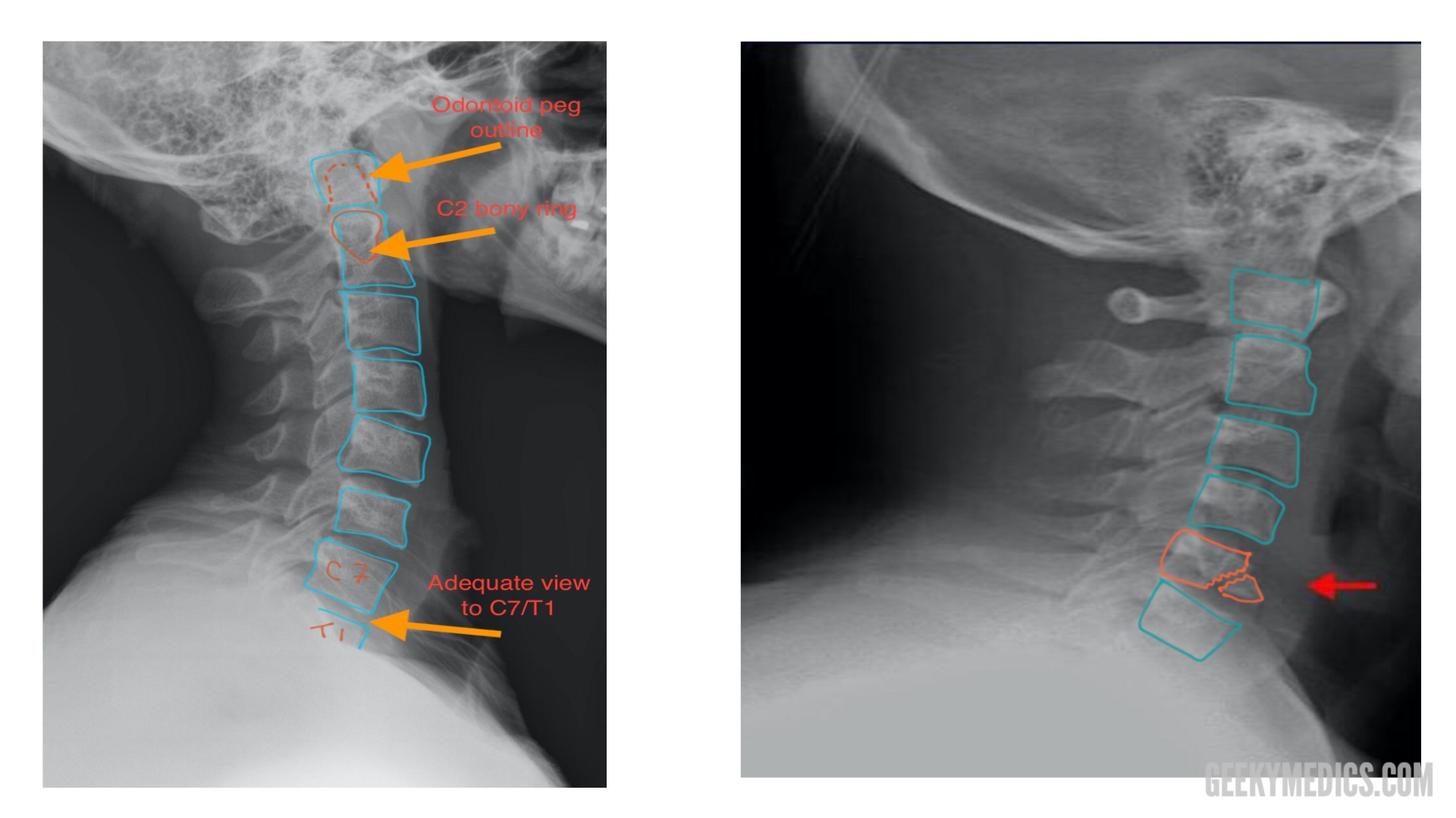
Check the radiograph’s adequacy to ensure you are able to clearly see all relevant structures (you should be able to see from C1 down to the C7/T1 junction).
Alignment
There are multiple lines you need to assess across each of the three radiograph views which should run uninterrupted in healthy individuals.
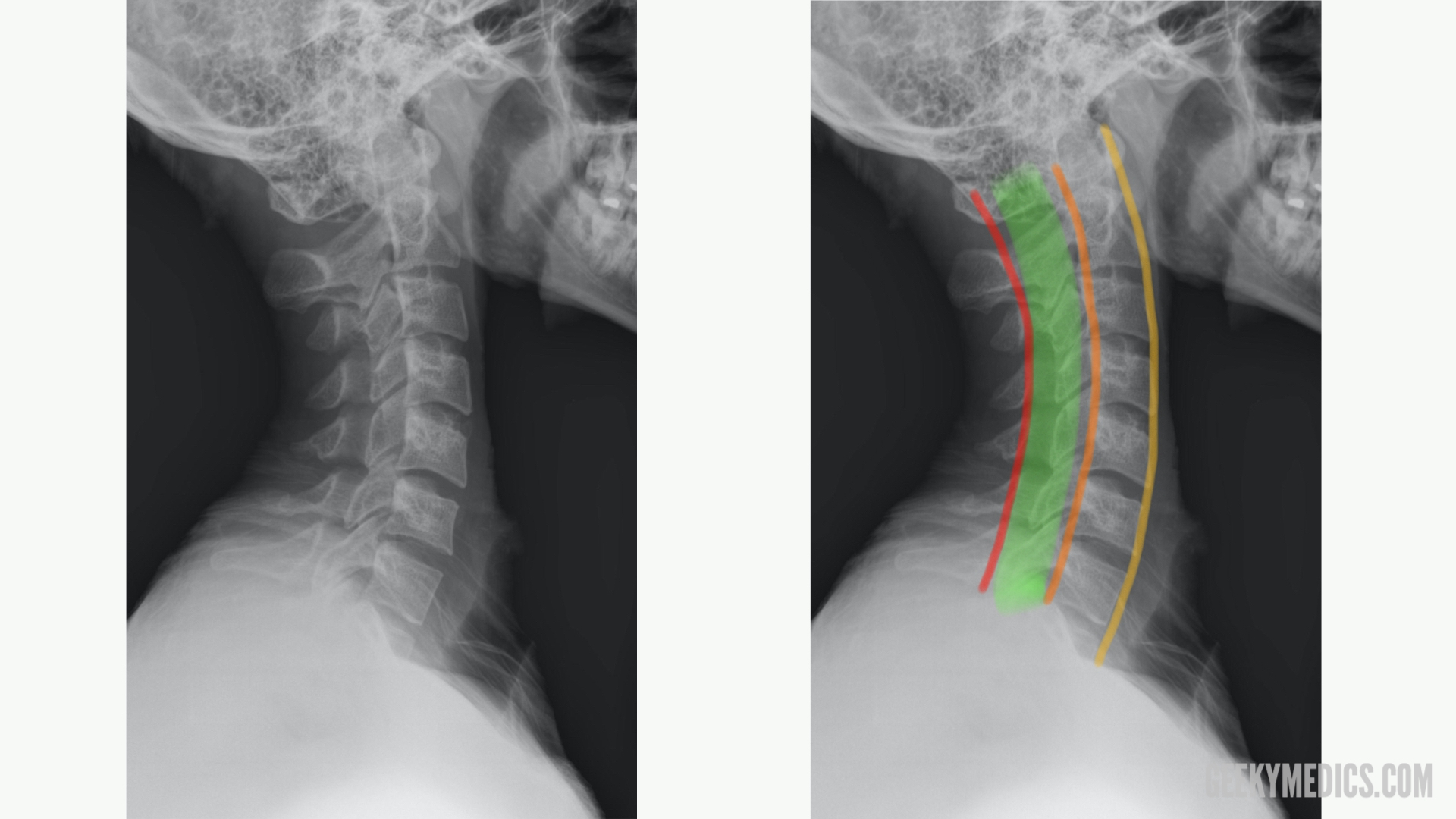
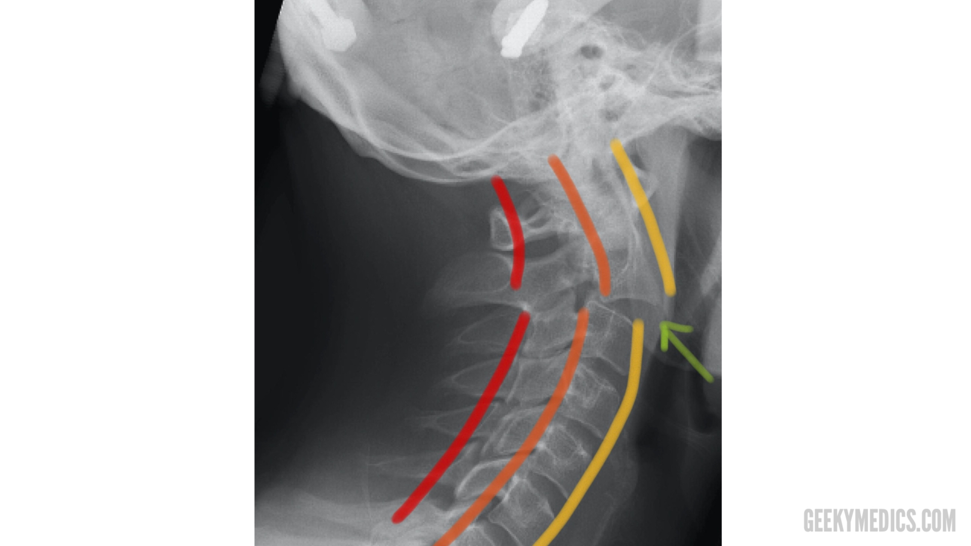
Lateral view
The anterior longitudinal line runs along the anterior surface of the vertebral bodies.
The posterior longitudinal line runs along the posterior surface of the vertebral bodies.
The spinolaminar line runs along the anterior edge of the spinous processes (at the junction of the spinous process and the laminae).
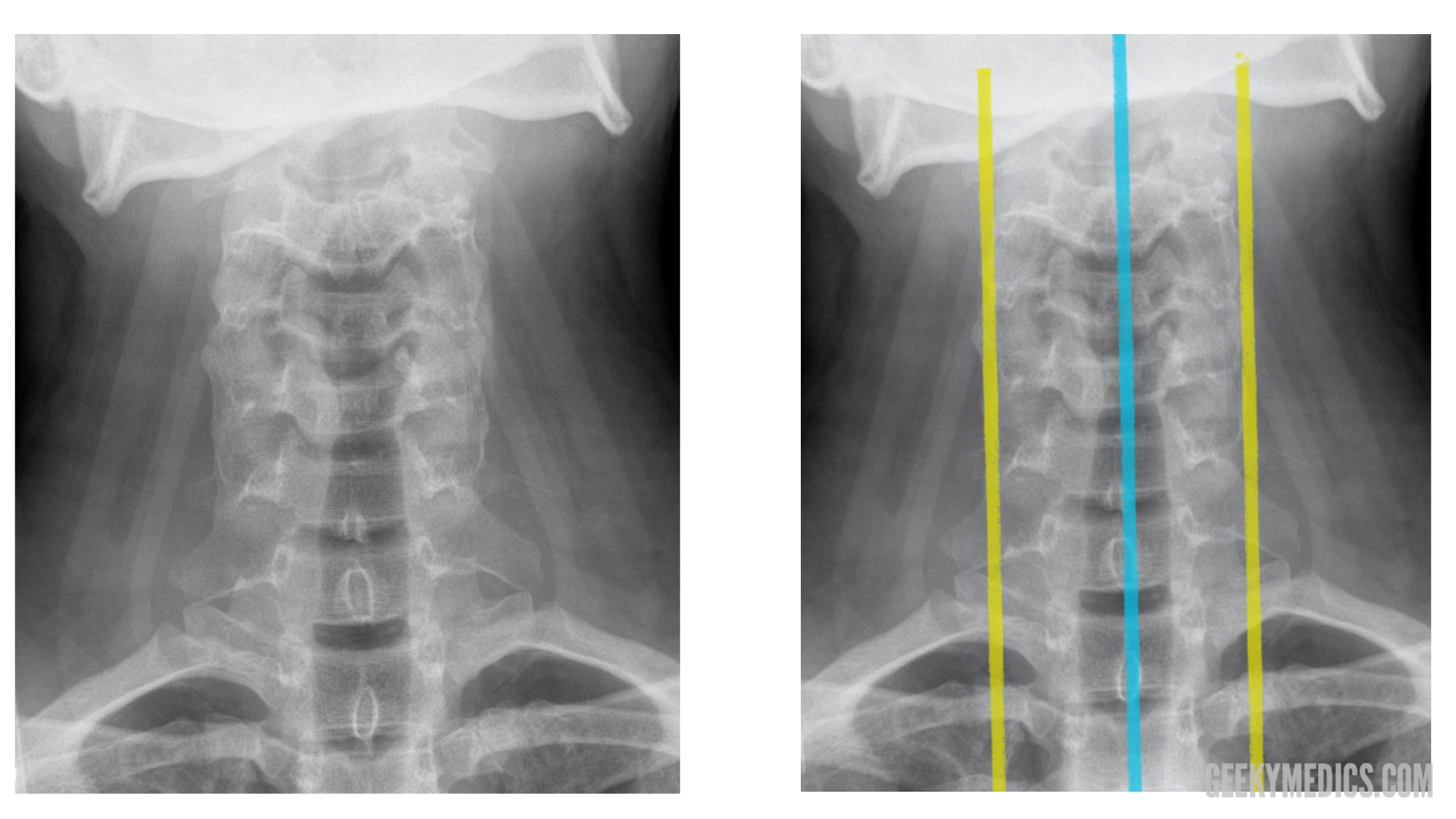
Antero-posterior (AP) view
The two lateral lines of the AP view run down either side of the vertebral bodies (represented by the yellow lines in the image below).
The spinous process line runs down through each spinous process from C1 to C7 (represented by the blue line in the image below).
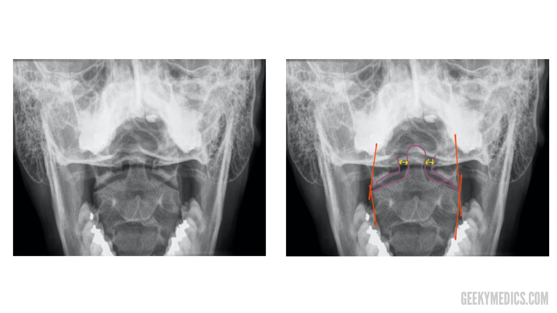
Odontoid/open-mouth view
The odontoid/open-mouth view has several intersecting lines which are sometimes referred to as a “meeting of corners”. Irregularities in the areas where these lines intersect may indicate misalignment of the lateral masses of C1 and C2 (e.g. fracture, dislocation).
You can also use this view to assess the odontoid peg to make sure it is aligned with the lateral masses of C1. To do this, inspect and compare the space between the peg and the lateral mass of C1 on each side. Asymmetry of the space between the peg and the lateral mass of C1 may indicate fracture or dislocation of the odontoid peg.
Bones
In all three of the previously discussed views, you should carefully inspect the cortex (outer white edge) of each bone in turn, making sure you are systematic (e.g. top to bottom) in your approach. A common pitfall is to stop searching once you have found one abnormality. If an abnormality is identified, you should note it and then continue to follow your systematic approach until all relevant bones have been assessed.
Tips
The odontoid peg: as well as on the odontoid view, the peg can usually be viewed on lateral views as an increased area of density within the body of C1. Make sure you include this in your scan of the cortices of each bone.
Inside the body of C2, there is a radio-dense (“whiter”) ring of bone, which represents the lateral masses of C2. A fracture of the lateral masses of C2 would be visible on X-ray as a disruption of the C2 bony ring.
Cartilage (i.e discs)
Intervertebral discs should be roughly similar in height throughout the cervical spine, with no obvious loss of height at any point in the disc. However, if you suspect disc pathology (e.g disc herniation) from the history/examination (cervical radiculopathy with sensory/motor disturbance at a certain spinal level), this often wouldn’t be clearly seen on a cervical spine X-ray and would be better investigated with an MRI scan.
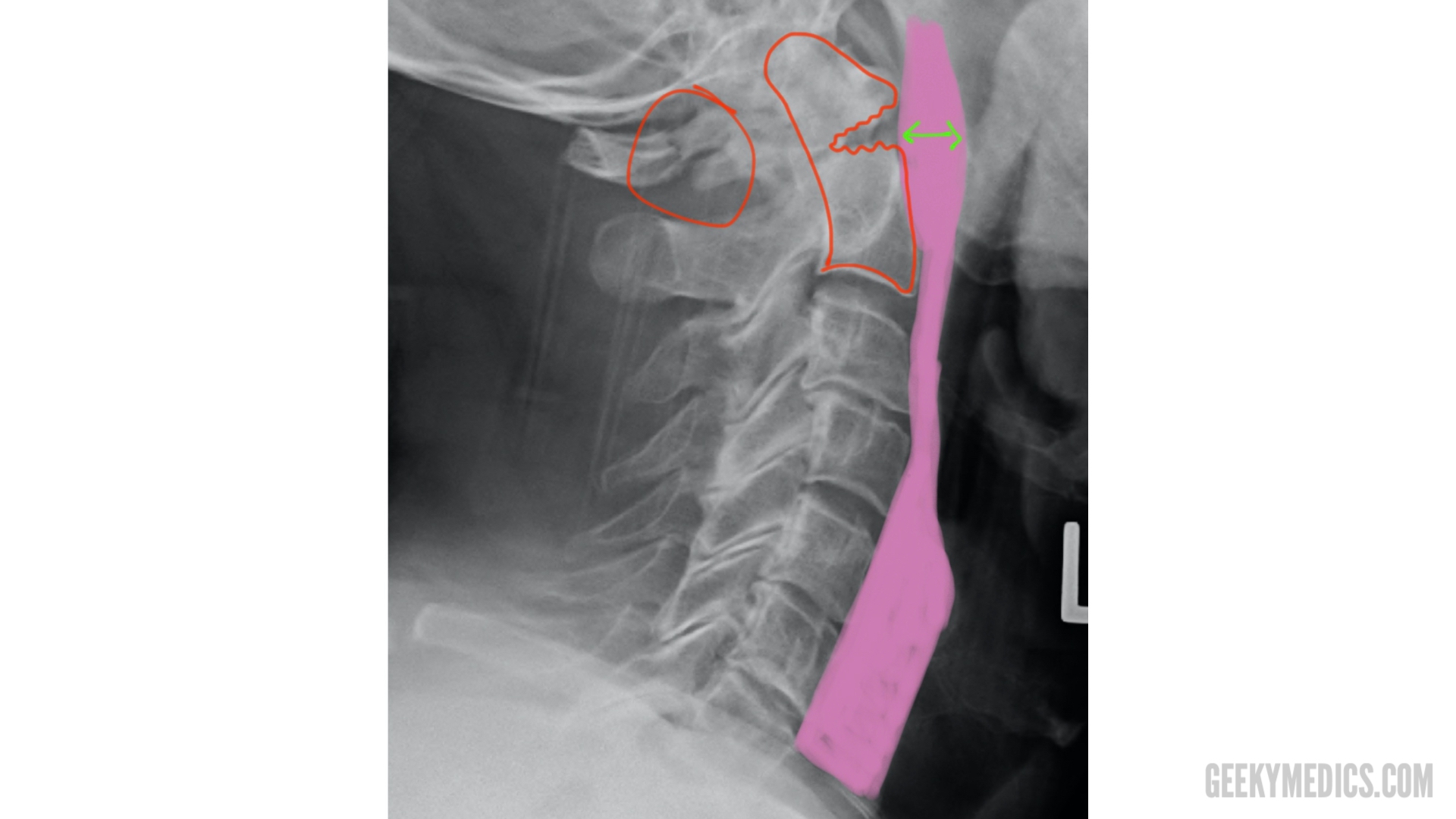
Soft tissue
Pre-vertebral (i.e the area directly anterior to the vertebral bodies) soft tissue is best assessed using a lateral view. Soft tissue appears as a light grey opacity on cervical spine X-rays, located between the vertebral bodies and the darker-grey area that represents the trachea. Any widening of this space may represent a pre-vertebral haematoma and should significantly raise suspicion of a cervical fracture. It should be noted that this area naturally gets wider around the level of C4 so two different acceptable widths are used:
- above C4 the pre-vertebral soft tissue should be no larger than one-third of the adjacent vertebral body in width.
- from C4 onwards the pre-vertebral soft tissue should be no larger than the width of one whole vertebral body.
If a lateral cervical spine X-ray has been requested for another indication (e.g. suspected foreign body in the trachea) you should make sure you include these other structures in your assessment of the radiograph.
Summary
When interpreting a cervical spine X-ray, begin by confirming the patient’s details, reviewing the clinical history and ensuring the radiographs are adequate.
You may find it useful to have a mnemonic such as ABCs when interpreting the X-ray:
- Alignment: assess the alignment of all relevant views (e.g. lateral, AP and open mouth).
- Bones: assess each of the vertebrae, inspecting the cortex for irregularities.
- Cartilage: assess the height of each intervertebral disc.
- Soft tissue: assess the pre-vertebral soft tissue width, for evidence of swelling.
Reviewer
Dr Edward Twimasi
Consultant Radiologist
References
- Staff at the Department of Radiology, UC San Diego Health. Adapted by Geeky Medics.
- Lucien Monfils. Adapted by Geeky Medics. Hangman’s fracture. Licence: CC BY-SA 3.0. Available from: [LINK].
- Moquito 17. Teardrop fracture. Adapted by Geeky Medics. Licence: CC BY-SA 3.0. Available from: [LINK].
- James Heilman, MD. Adapted by Geeky Medics. Licence: CC BY-SA 4.0. Available from: [LINK].
